
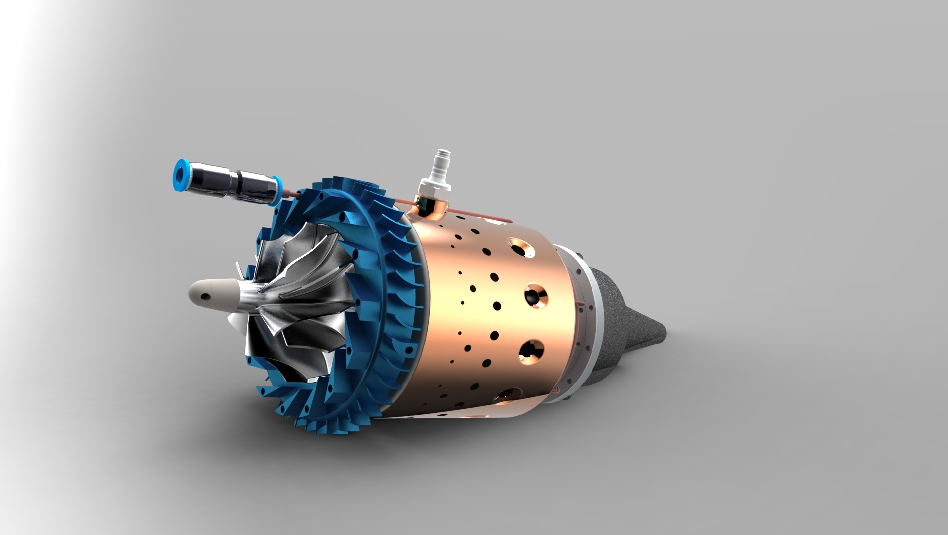

Assembling the combustion chamber of the KJ-66 turbojet engine:
1. Welding the Main Chamber Body The sheet metal parts of the combustion chamber (recommended Inconel 600 or an equivalent like SS 310) must be joined together. To hold the combustion chamber together securely, TIG welding is highly recommended as it will undoubtedly give far better results than spot welding.
2. Preparing and Attaching Vaporizer Sticks You need to make the vaporizer sticks [5.4] out of 6 x 0.3mm stainless steel tubes. These must be attached to the combustion chamber back part [5.5], which can easily be done using either a spot welder or TIG welding.
3. Assembling with Wire Loops and Struts The basic assembly of these combustion chamber components is completed and held together using 6 wire loops [5.9]. Note on Ignition: If you do not plan to use an ignition system, you must mount two combustion chamber struts [5.7] at opposite points on the combustion chamber exterior part [5.3], rather than the standard single strut.
4. Installing and Adjusting the Fuel and Gas Pipes Clip the fuel pipe assembly and the starting gas assembly onto the combustion chamber.
- Crucial Adjustment: You must carefully adjust the injector tubes [7.4] and [8.4] so they insert exactly into the vaporizer sticks [5.4]. These injectors must be inserted so that they touch the walls of the tubes, positioned approximately 3mm from the front.
- Pipe Bending: Bend the fuel pipe [7.2] and the starting gas pipe [8.3] to form an “S” loop, ensuring the connectors [7.1] and [8.1] align close to their corresponding holes in the engine casing.
5. Inserting into the Casing and Final Securing Insert the fully piped combustion chamber into the engine casing. Secure the chamber in place using M3 screws [14.4] and the glow plug (which threads into part [6.2]) along with the combustion strut [5.7]. Finally, pass the fuel and gas connectors [7.1, 8.1] through their respective casing holes and fasten them with washers and nuts.