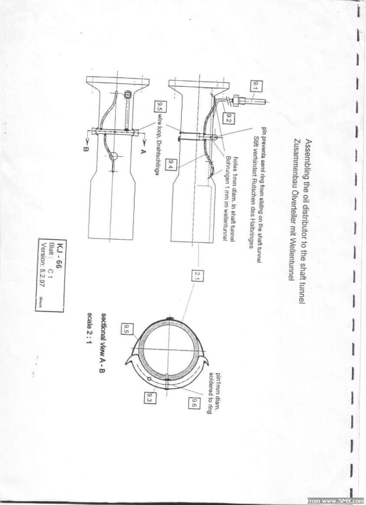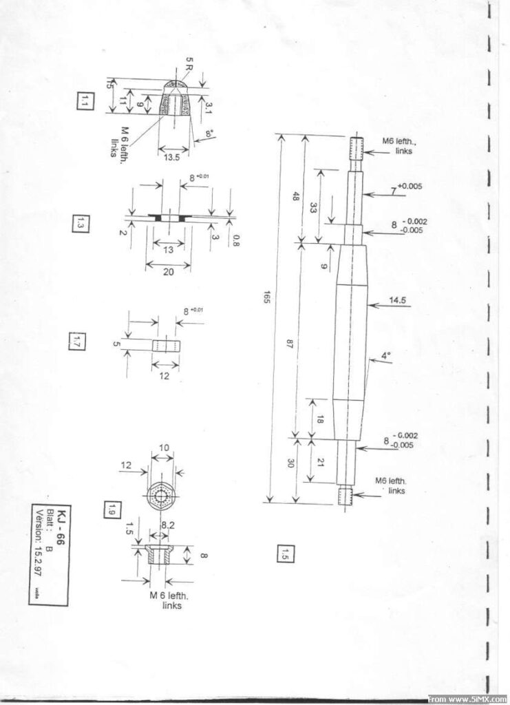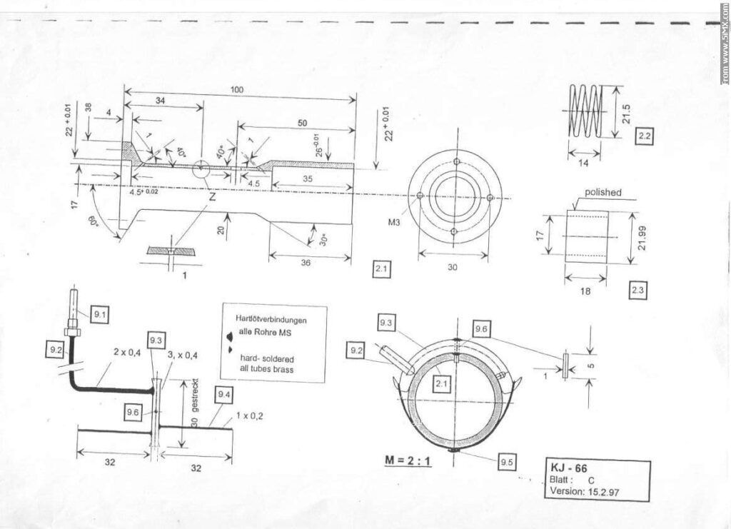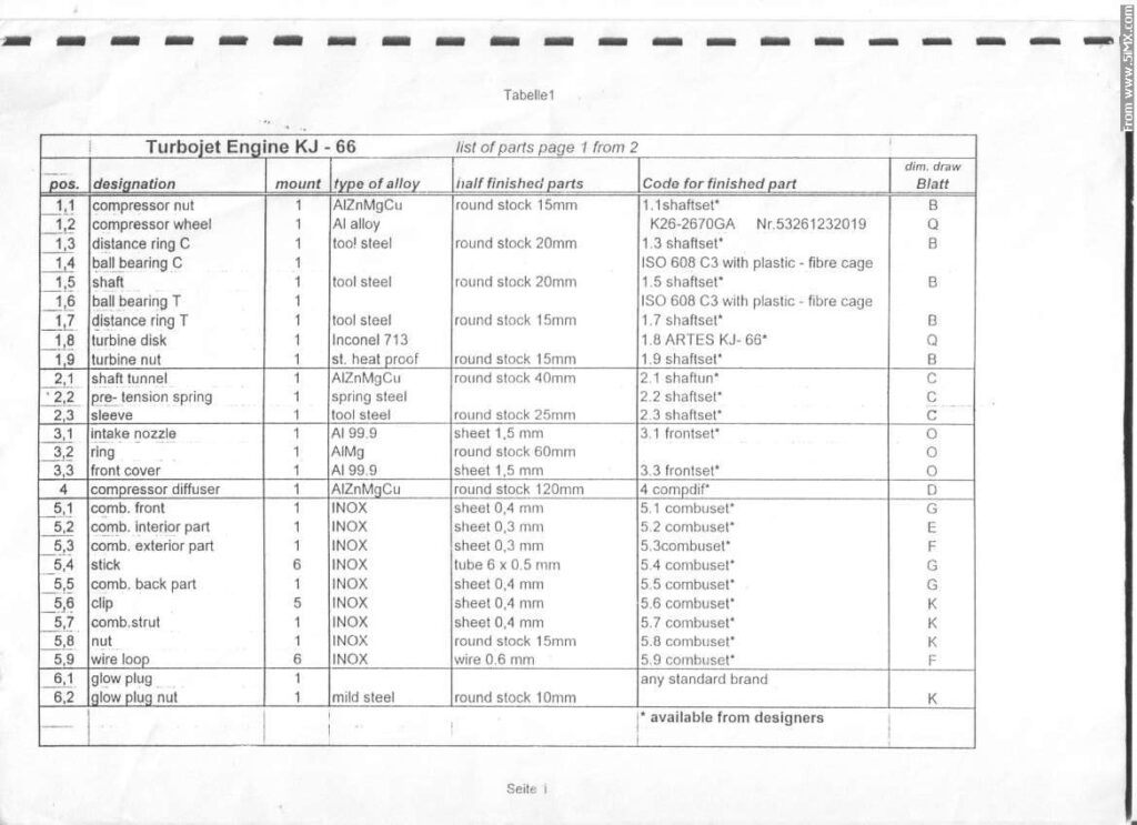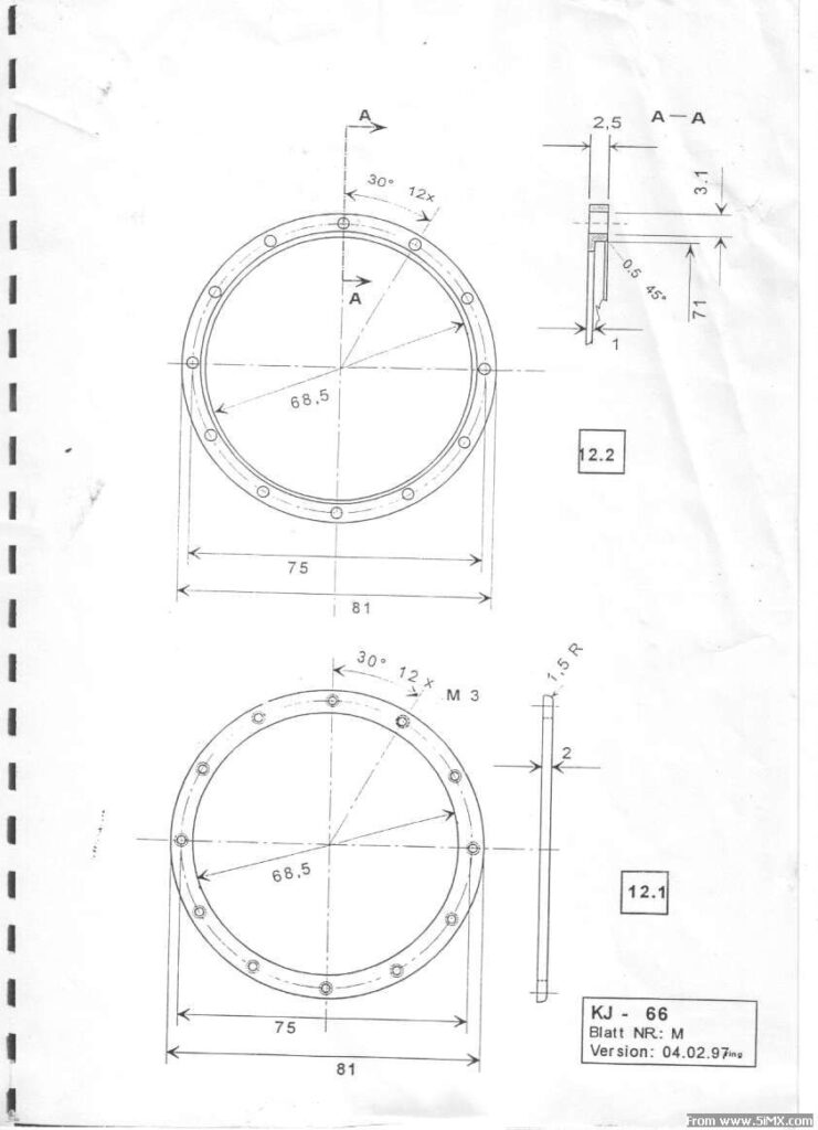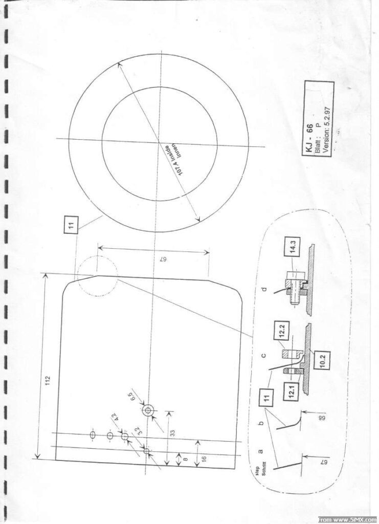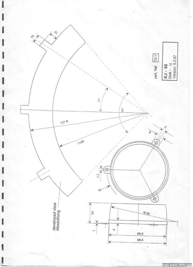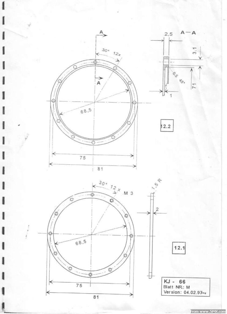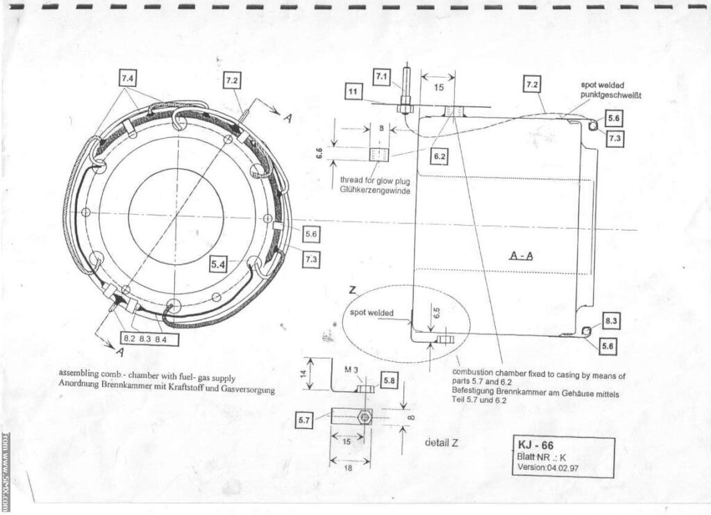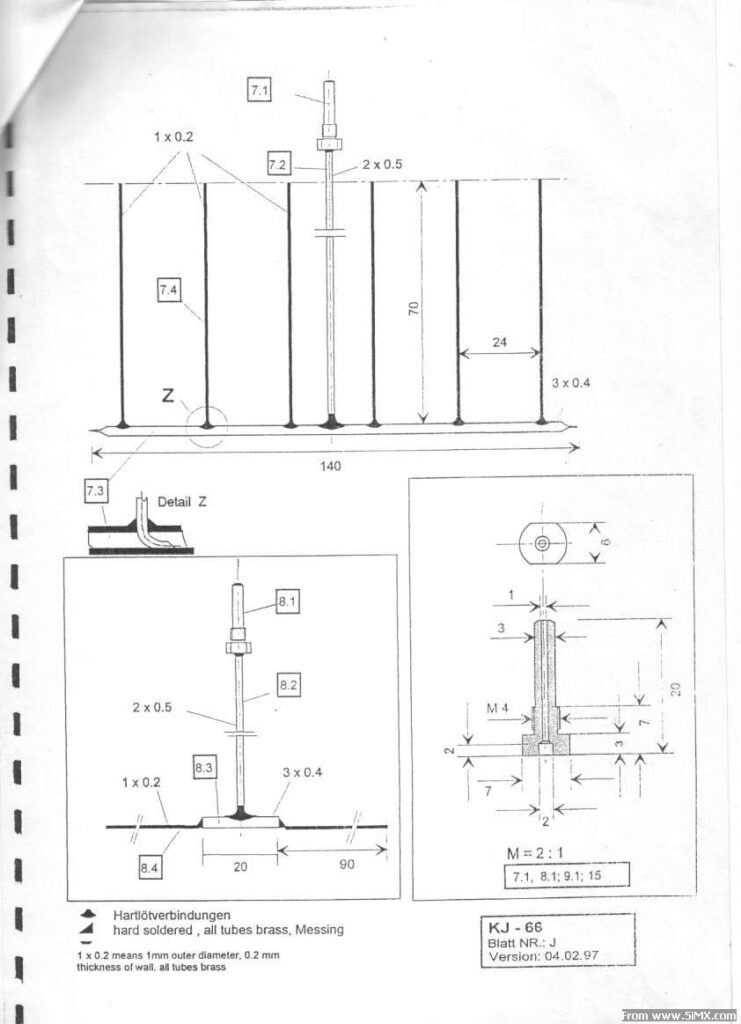
Assembling the combustion chamber of the KJ-66 turbojet engine:

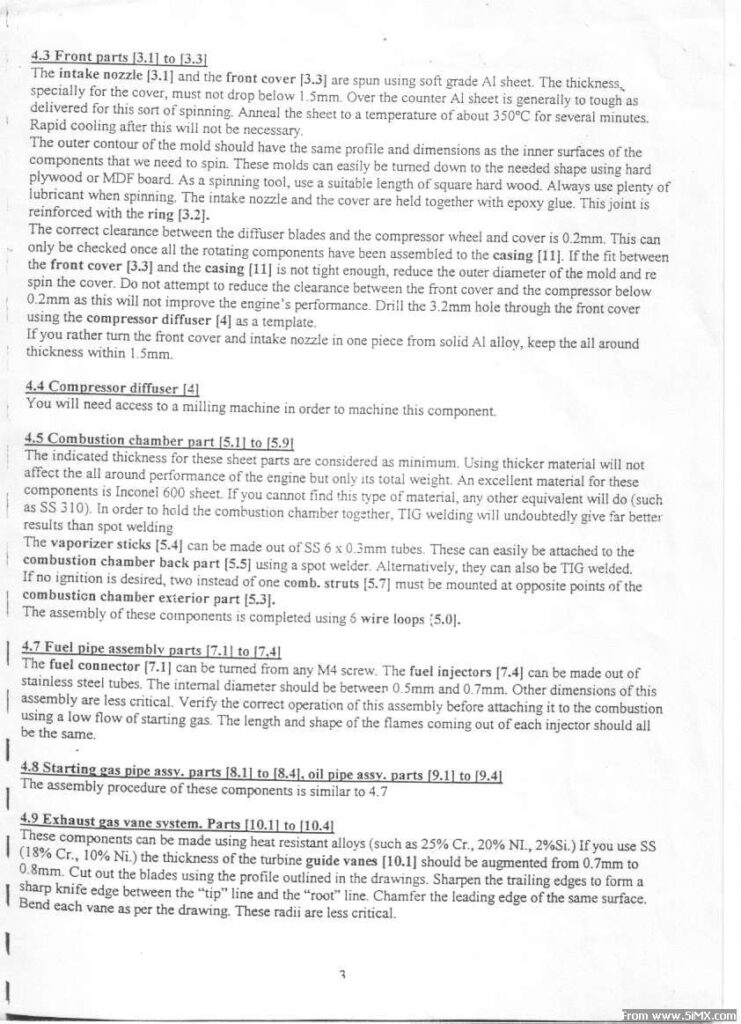
1. Welding the Main Chamber Body The sheet metal parts of the combustion chamber (recommended Inconel 600 or an equivalent like SS 310) must be joined together. To hold the combustion chamber together securely, TIG welding is highly recommended as it will undoubtedly give far better results than spot welding.

2. Preparing and Attaching Vaporizer Sticks You need to make the vaporizer sticks [5.4] out of 6 x 0.3mm stainless steel tubes. These must be attached to the combustion chamber back part [5.5], which can easily be done using either a spot welder or TIG welding.

3. Assembling with Wire Loops and Struts The basic assembly of these combustion chamber components is completed and held together using 6 wire loops [5.9]. Note on Ignition: If you do not plan to use an ignition system, you must mount two combustion chamber struts [5.7] at opposite points on the combustion chamber exterior part [5.3], rather than the standard single strut.

4. Installing and Adjusting the Fuel and Gas Pipes Clip the fuel pipe assembly and the starting gas assembly onto the combustion chamber.

  • Crucial Adjustment: You must carefully adjust the injector tubes [7.4] and [8.4] so they insert exactly into the vaporizer sticks [5.4]. These injectors must be inserted so that they touch the walls of the tubes, positioned approximately 3mm from the front.
  • Pipe Bending: Bend the fuel pipe [7.2] and the starting gas pipe [8.3] to form an “S” loop, ensuring the connectors [7.1] and [8.1] align close to their corresponding holes in the engine casing.

5. Inserting into the Casing and Final Securing Insert the fully piped combustion chamber into the engine casing. Secure the chamber in place using M3 screws [14.4] and the glow plug (which threads into part [6.2]) along with the combustion strut [5.7]. Finally, pass the fuel and gas connectors [7.1, 8.1] through their respective casing holes and fasten them with washers and nuts.
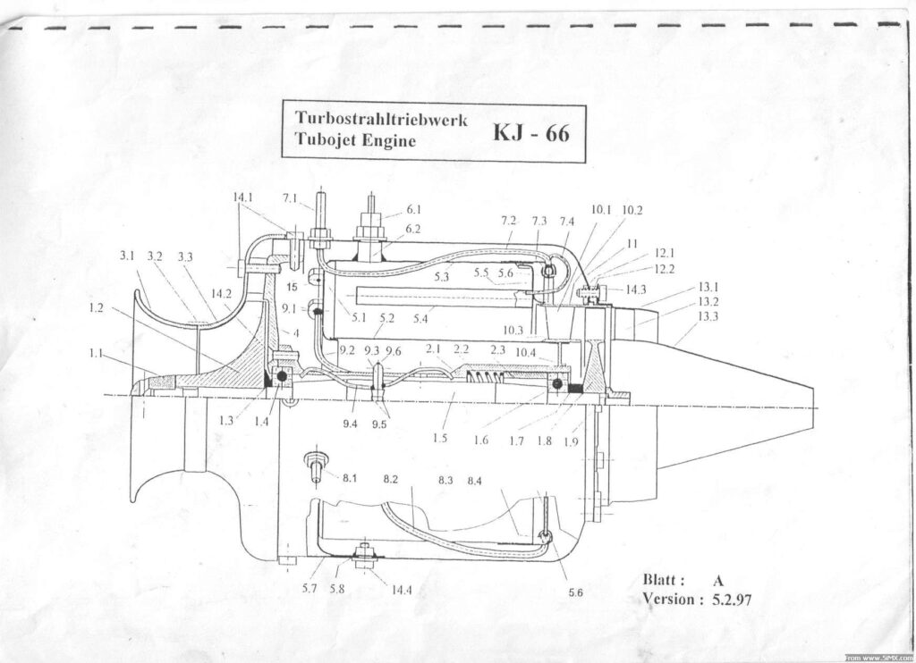
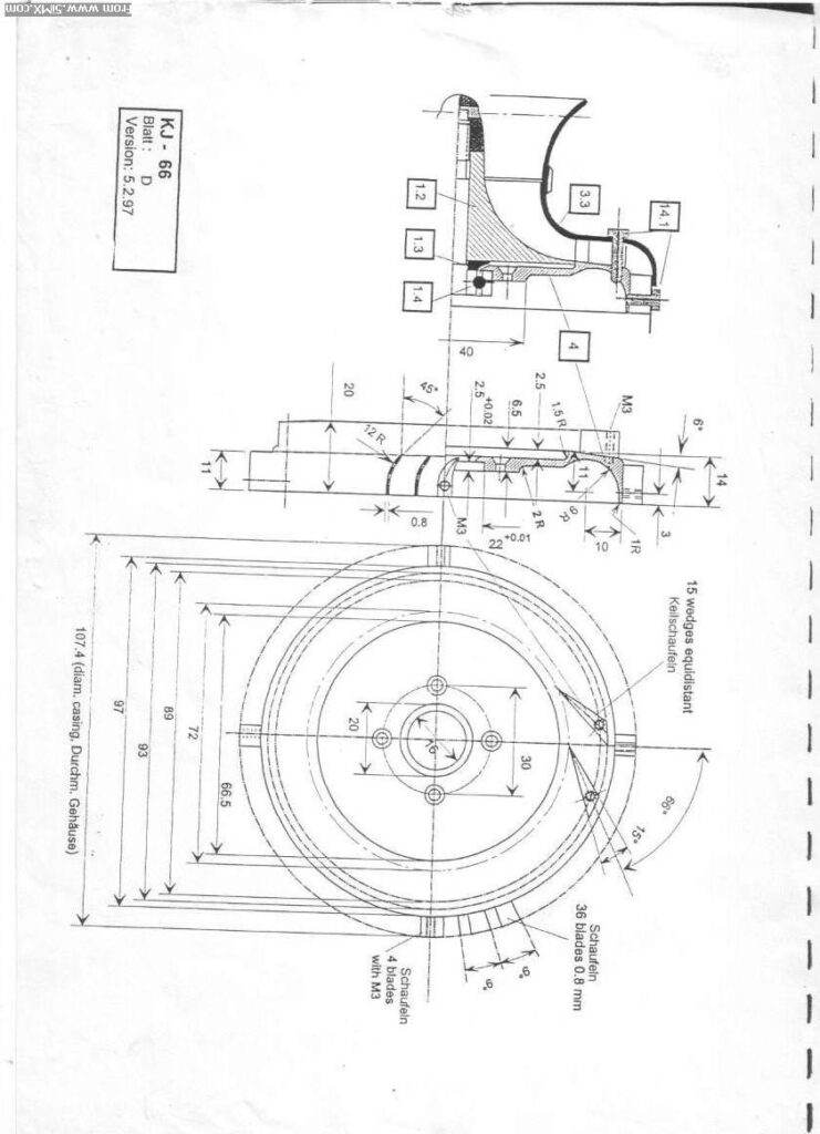
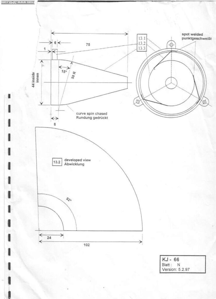
KJ-66 engine Detail drawing

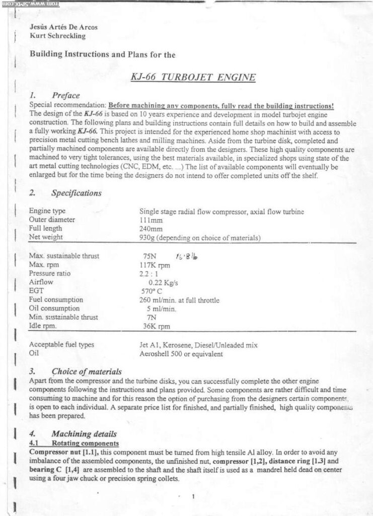
The KJ-66 is a miniature turbojet engine specifically designed for experienced home shop machinists with access to precision metal cutting lathes and milling machines. It was designed by Jesús Artés De Arcos and Kurt Schreckling.

1. Engine Type & Core Structure

  • Design: The engine features a single-stage radial flow compressor and an axial flow turbine.
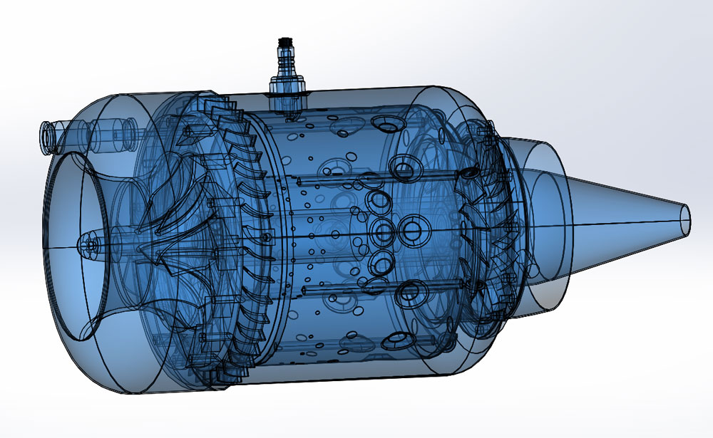
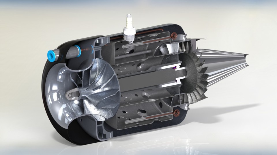
  • Layout: According to the cross-sectional blueprint, air enters through the front intake, is compressed by the compressor wheel, and enters the central combustion chamber where it mixes with fuel. The expanding exhaust gases drive the rear turbine (which powers the compressor via a shaft) before exiting the nozzle to create thrust.

2. Core Specifications

  • Dimensions & Weight: The engine has an outer diameter of 111mm, a full length of 240mm, and a net weight of approximately 930g (depending on the choice of materials).
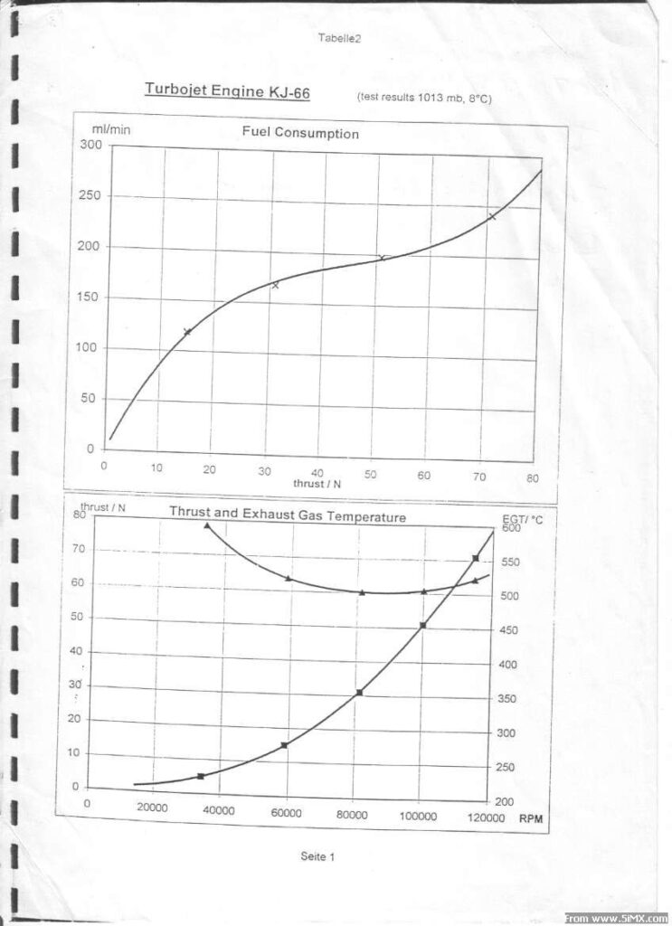
  • Thrust Performance: It generates a maximum sustainable thrust of 75N and has a minimum sustainable thrust of 7N.
  • RPM & Aerodynamics: The engine reaches a maximum speed of 117,000 RPM and idles at 36,000 RPM. It has a pressure ratio of 2.2:1 and processes an airflow of 0.22 Kg/s.
  • Temperature: The nominal Exhaust Gas Temperature (EGT) is 570°C. Test result graphs show that both thrust and EGT increase significantly as the RPM climbs toward its maximum.

3. Fuel & Lubrication System

  • Fuel: The engine can run on Jet A1, Kerosene, or a mix of Diesel and Unleaded gasoline. At full throttle, fuel consumption is 260 ml/min.
  • Lubrication: It uses Aeroshell 500 or equivalent oil, with an oil consumption rate of approximately 5 ml/min.

4. Key Components & DIY Characteristics Because this project is intended for home builders, the design incorporates clever, easily accessible materials:

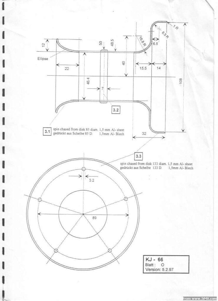
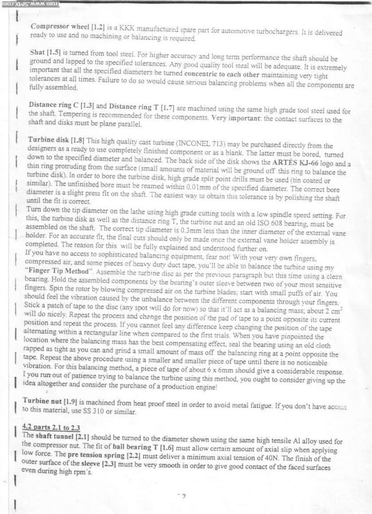
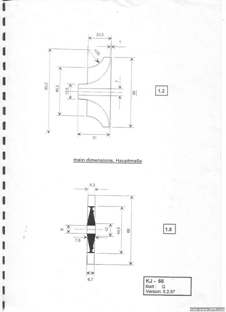
  • Compressor Wheel: Builders do not need to machine or balance this part; the plans specify using a KKK-manufactured spare part originally made for automotive turbochargers.
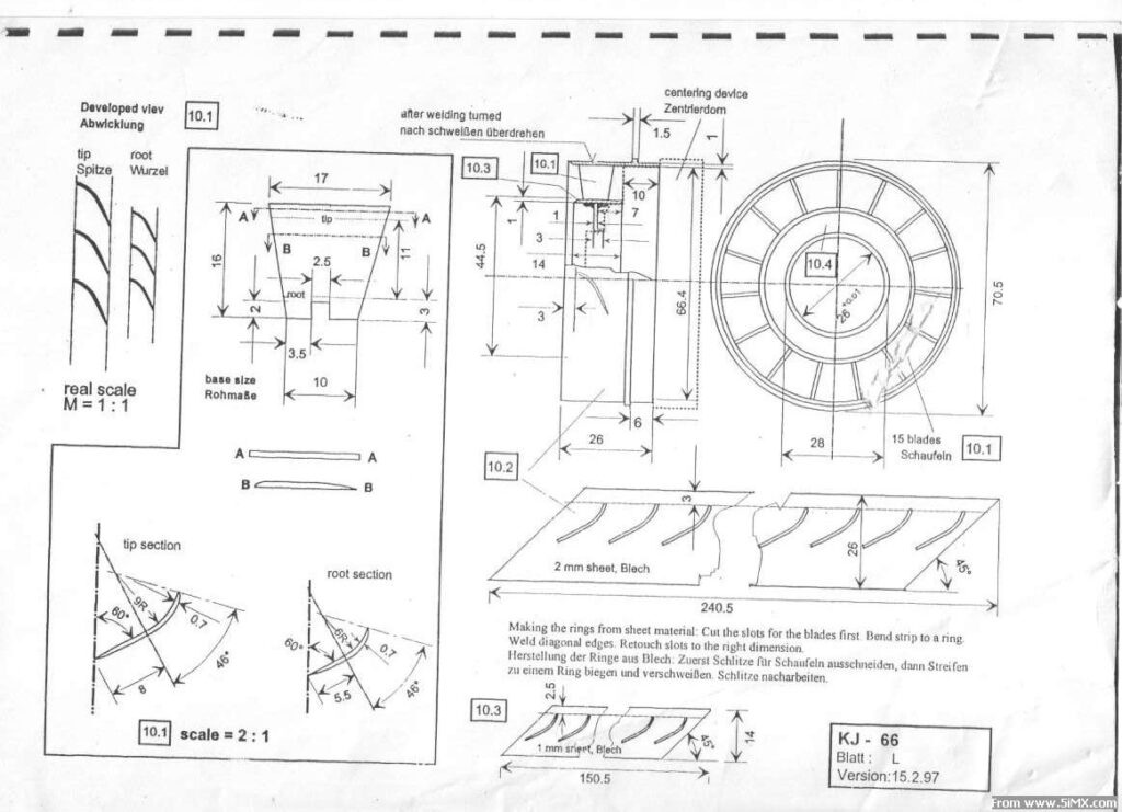
  • Turbine Disk: This is a critical high-temperature component cast from INCONEL 713. It can be purchased directly from the designers as a finished part or as a blank that requires careful machining and balancing.
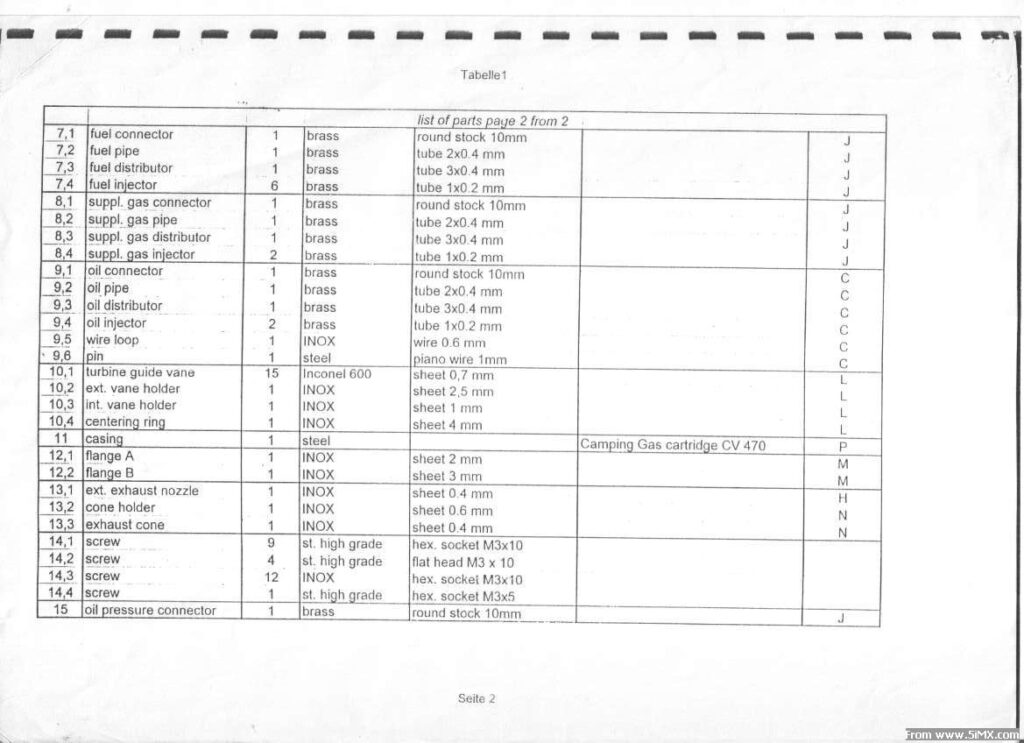
  • Engine Casing: In a highly resourceful design choice, the main engine casing is made by modifying an empty CV 470 Camping Gas cartridge. Builders simply remove the factory paint and machine the ends to specific dimensions.
  • Combustion Chamber: Manufactured using thin INOX sheet metal (0.3mm to 0.4mm thick) or equivalents like SS 310 or Inconel 600. The parts are held together using spot welding or TIG welding.
KJ-66 micro turbojet engine

This is a beautifully detailed cutaway CAD rendering of a KJ-66 micro turbojet engine.

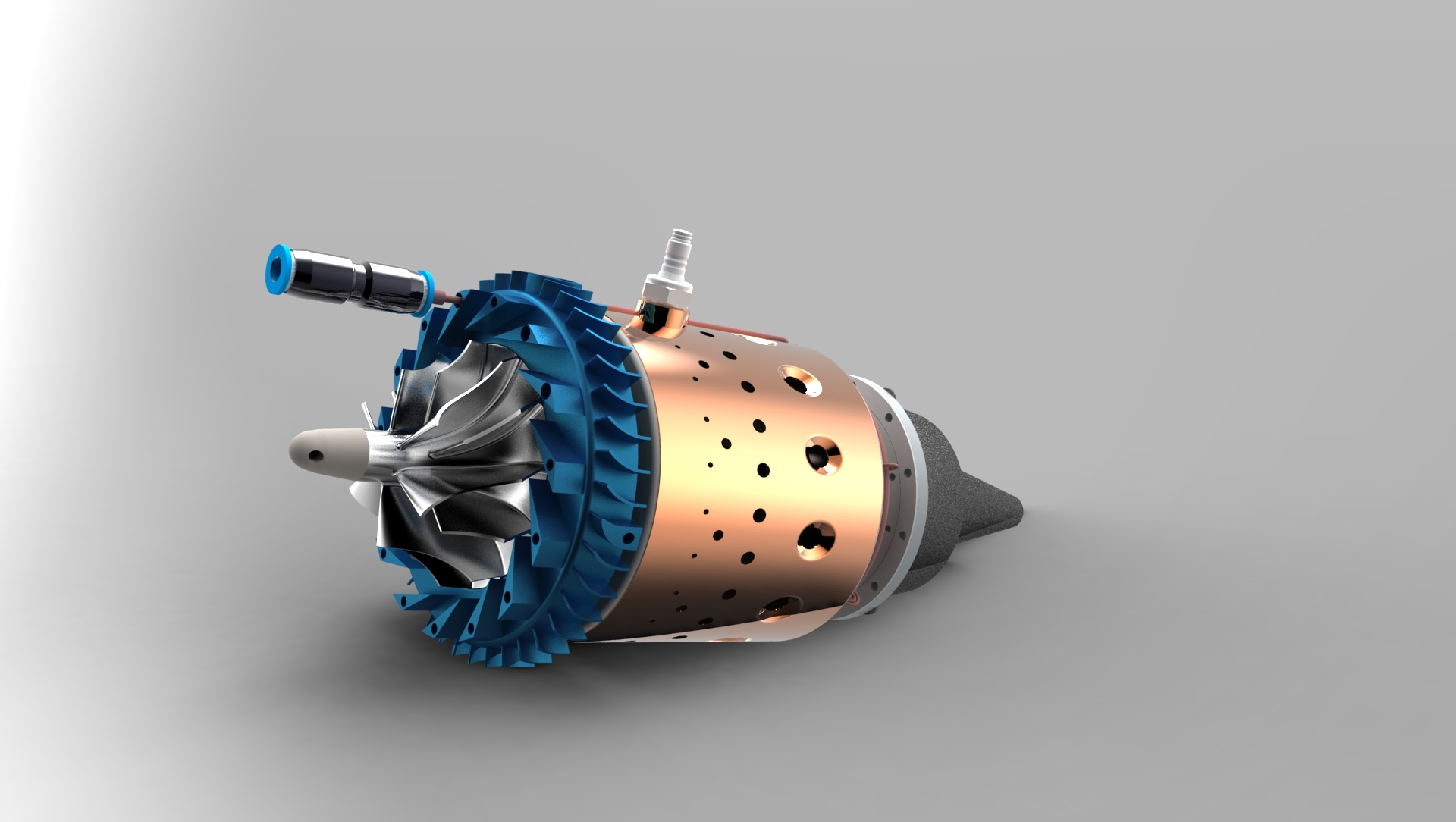
The KJ-66 holds a milestone position in the history of micro turbojets, especially within the realms of aeromodelling and micro-UAVs. Jointly designed by aviation enthusiasts Kurt Schreckling and Jesus Artes (the name comes from their initials), its open-source blueprints, classic structure, and ease of manufacturing made it the “godfather” and foundational design for countless commercial model aircraft turbine engines worldwide.

Based on the cutaway view you provided, we can clearly break down its core structure and working principles from left to right (following the airflow from intake to exhaust):